Modifying the Pre-Mid-2004 SkyView Pro
Equatorial Mount for Autoguiding
by Dave Rosenthal
I have owned an Orion SkyView Pro mount with dual axis drives for about 6 months now and wanted to share my experiences with the mount and what I have done to optimize its performance as an astrophotography platform.
The first thing I did, before even mounting an OTA to it was to mechanically overhaul the mount.Ā I started by reading the Modifying the SkyView Pro Mount (http://www.andysshotglass.com/SVPmods.html) article on AndyÆs web site.Ā I followed the instructions to the letter and it made a huge difference to the motions in both the RA and DEC axis.Ā I received the most benefit from these 4 steps:
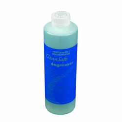
- Disassemble the entire mount and degrease everything.Ā I used an environmental friendly organic degreaser used by bicycle mechanics (my other hobby!).Ā Quite effective and available from Performance Bicycle. http://www.performancebike.com/shop/profile.cfm?SKU=358&subcategory_ID=4205
- Using my Dremmel rotary tool and a small wire wheel, I deburred the entire leading edge of the supr gears.Ā This helps the worm mesh and ride more smoothly around the spur
- Relubricate all appropriate surfaces with white lithium grease.Ā This is easily obtained from any general hardware store.Ā I used just enough to evenly coat the surfaces.
- Reassemble the mount paying extra attention to the worm-spur mesh and the drive motor gear mesh.Ā I spent multiple nights getting this just so. I would adjust the mesh, set up the imaging equipment, take a few test shots.Ā Then evaluate the stars and repeat as necessary until I could no longer see any improvement.Ā This was a critical part of the rebuild and I believe is reason I can achieve 300 second (5 minute!) sub-exposures without any sign of trailing or elongation.Ā Here are 2 examples of what I was able to achieve after this procedure and adding autoguiding capability to the mount
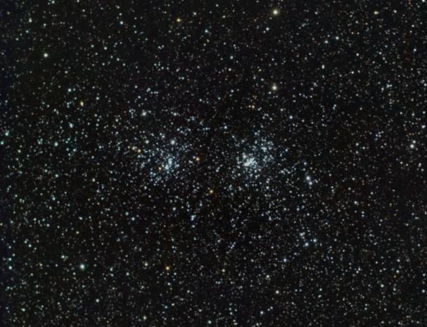
The Double Cluster in Persius.
Imaged with a 300D through a William Optics ZS66SD with 0.8 FR.FF
Guided with a DSI Pro I and a Sigma 55-200mm lens
Sigma Clip stack of 17 3 minute ISO 800 Exposures
 Ā
Ā
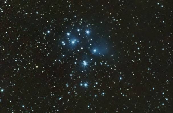
The Seven Sisters in the Pleiades
Imaged with a Canon 300D through Sigma 55-200 lens
Guided with a William Optics ZS66SD and a DSI Pro I
Sigma Clip stack of 21 5 minute ISO 800 Exposures
To make the SVP mount able to be autoguided is really a straight forward
and simple procedure which is done in 2 parts.
1.
Modify the Dual Axis Drive hand controller to access
a ST-4 port.Ā I used an excellent
Step-By-Step instruction written by Doug Anderson at Shoestring Astronomy
which I am including here in its entirety:

www.shoestringastronomy.com
Modification
of a EQ-style Dual Axis Controller
to Add an
Autoguider Port
Revision 1.0
Copyright 2004, Shoestring Astronomy
INTRODUCTION
The EQ-style telescope mount series are some of the most widely sold mounts in the world.Ā Various companies such as Celestron and Orion sell versions of these mounts.Ā They are all produced by Synta.
By adding on the motor and handcontroller accessories that are available for these mounts, long-exposure manually-guided astrophotography can be performed.Ā However, these handcontrollers do not include autoguider ports so that computer driven autoguiding can be utilized.
There is no standardized autoguider port that is common to all manufacturers, but the so-called ST4 port is a very common format used on most scopes.
These instructions document a procedure that was used to modify an EQ3 dual-axis handcontroller to add an ST4-style autoguider port.Ā The CG-5 mount that it was attached to was then successfully used to perform astrophotography using GuideDog software from barkoSoftware (www.barkosoftware.com).Ā Guiding error was kept below +/- 4 arc-seconds.Ā Besides your modified handcontroller and the guiding software, you will need a suitable webcam, a computer near your telescope, a guide port interface such as model GPINT-PT from Shoestring Astronomy, and a cable to go from the interface to the handcontroller.Ā Shoestring Astronomy also sells a kit with the parts you will need to make this modification.
If you own one of these styles mounts, and are comfortable with opening up the handcontroller box and making some simple modifications, then read on!Ā If you are not comfortable doing this, maybe you have a friend that is.Ā Webcam autoguiding is an inexpensive way to eliminate the monotony of manually autoguiding.
Read through these instruction entirely prior to beginning the modification.Ā Make sure you understand what must be done, and are completely comfortable with doing it.
WARNING
Performing this modification will void your warranty.Ā Do not proceed if you are not comfortable with this.Ā Also, all work should be performed by a person who knows how to solder, and at a workstation that is electrostatic-discharge (ESD) safe.Ā Failure to do so may result in permanent damage to your handcontroller.Ā This procedure is not particularly difficult, but should not be performed by someone unfamiliar with electronic assembly.
TOOLS and SUPPLIES NEEDED
- Kit of parts GPKIT-EQ from Shoestring Astronomy or equivalent.
- 7/32ö nutdriver
- 7/32ö drill bit
- Drill
- Tweezers
- Two flat screwdrivers
- Small Phillips screwdriver
- Solder iron
- Eutectic solder
PROCEDURE
1)Ā Test your handcontroller using your scope mount and the power pack first to make sure it is functioning properly prior to making any changes.
2)Ā Unplug the handcontroller from the scope mount and the power pack.
3)Ā Carefully remove the four directional control button caps.Ā Using two flat screwdrivers inserted from opposite sides as shown in Figure 1, gently pry up evenly from both sides until the button cap pops loose.
4)Ā Remove the two screws on the lower side of the handcontroller that hold the power jack in place, see Figure 2.
5)Ā Remove the four screws that hold the top cover, see Figure 3.
6)Ā Remove the cover.
7)Ā Remove the two screws that hold the keypad in place, see Figure 4.
8)Ā Flip the keypad over.
9)Ā Remove the three screws that
hold the main board, see Figure 5.
10)Ā Carefully lift the main board out.Ā You may need to pull some of the motor cable through their holes to do this.
11)Ā Using a nutdriver from the
top, and a screwdriver from the bottom, remove the two screws that hold
the cable strain relief in place, see Figure 6.
12)Ā Drill a 7/32ö hole in the
lower side of the enclosure in the location shown in Figure 7.Ā While drilling, hold all parts internal to
the handcontroller out of the way so that they will not be damages when
the drill bit comes through the enclosure.Ā
This step is best performed with the help of another person.
13)Ā Push the stripped end of the cable from the parts kit through the hole far enough so that you can still keep the main board flipped up.
14)Ā Using the original screws
and nuts, replace the strain relief bar with all three cables underneath
it as shown in Figure 8.Ā You
should leave about 4 inches of the new cable out past the strain relief
so that it will easily reach to the keypad.
15)Ā Put the main board back in place and replace the three screws that held it down.Ā Pull the cables back out through their holes as necessary.
16)Ā Solder the five wires that come out of the end of the new cable to the locations on the underside of the keypad board as shown in Figure 9.Ā There is a sixth wire in the cable, but it is unused and has been trimmed back.
If you are not using the kit from Shoestring Astronomy, here is the way the cable wires must be attached.Ā Note the colors detailed here may not correspond to any cable other that the one included in the Shoestring Astronomy kit.
Pin 1 ¢ White ¢ not used, be sure it is properly trimmed so that it will not short to anything.
Pin 2 ¢ Black ¢ Common
Pin 3 ¢ Red ¢ RA+
Pin 4 ¢ Green ¢ Dec+
Pin 5 ¢ Yellow ¢ Dec-
Pin 6 ¢ Blue ¢ RA-
17)Ā Put the keyboard back in place and screw it down with the two original screws.
18)Ā Hook the box up to the telescope mount and power pack and test its operation prior to completing the rest of the re-assembly.Ā First test that all four directional pushbuttons still work.Ā Now, test the autoguide port by using the checkout procedure in the Guide Port Interface Adapter (GPINT-PT) User Manual.Ā Make sure that you start the GuideDog software and properly set up and initialize the parallel port prior to connecting the guide port interface adapter to the scope mount.Ā This connection is made by attaching the cable coupler that comes with the kit to the end of the guide port cable you have just added, then running another cable (available from Shoestring Astronomy) from the coupler to the guide port interface adapter.Ā Once it appears that everything is operating properly, remove the connections to the scope mount, power pack, and interface adapter, and continue to re-assemble the handcontroller.
19)Ā Replace the cover and screw it down with the four original screws.
20)Ā Replace the two power jack screws.
21)Ā Carefully align and snap down the four directional control buttons.
22)Ā Hook the box up to the telescope mount and power pack again and test for proper operation as explained in step 18.
23)Ā Go out and enjoy your autoguided scope mount!!
DISCLAIMER
This document is intended to be a guideline only.Ā Shoestring Astronomy will not be held responsible for any direct or consequential damage that may result while or from making this modification.Ā This work will be done completely at the ownerÆs risk.
END
OF INCLUDED DOCUMENT
2.
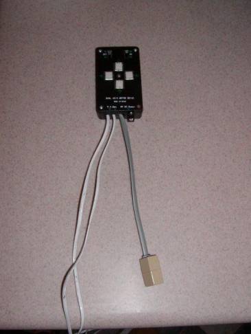
Purchase and install a Shoestring Astronomy GPUSB
autoguider interface module.Ā This
will connect to the ST-4 port you added to your handbox in step 1 above.
3.
Rig up a guide scope and camera to your SVP mount,
download and install PHD Guiding and you are ready for long exposure
astrophotography with your SVP Mount!!!
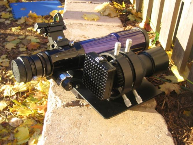
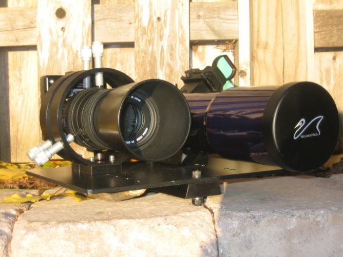
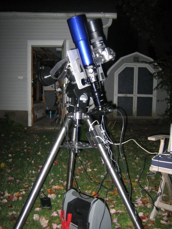
Here are some pictures of my new and improved SVP
mount and the side by side mounting for my imaging and guide optics: